
In my last post on firewall automation, I described the logical model I decided to use in order that I might be able to compute the path between endpoints using the Dijkstra shortest path algorithm. I’ve already discovered the handy Perl module module Paths::Graph that implements Dijkstra for me, so now all I need to do is to turn the network model into a data format that Paths::Graph will accept.
The Model
As a reminder, this is the model I’m using for my two-datacenter network:
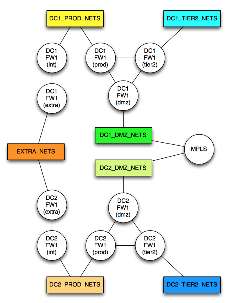
To model this network, I need to allocate a cost to every network link. It turns out that Paths::Graph wants me to create separate links in each direction; this is a huge pain, and makes an already risk-laden process doubly painful. After initially creating the data model directly in the code, I realized that it would be much simpler (hah!) to model the network using YAML, and to remove the requirement to include both directions of any link. In my new YAML mode, a link from A->B automatically implies a link from B->A with the same cost; this halves the number of link descriptions required, which I’ll take as a win. The format is dead simple:
---
DC1_PROD_NETS:
  - DC1FW1(int): 1
  - DC1FW1(prod): 1
DC1FW1(int):
  - DC1FW1(tier2): 1
  - DC1FW1(extra): 1
DC1FW1(tier2):
  - DC1_TIER2_NETS: 1
  - DC1FW1(dmz): 1
etc.
For each node, list the connected nodes and give a link cost. That YAML is then loaded into the perl script using the YAML::XS module, and processed to generate the data format required for the Graphs::Path module.
As a reminder, to ensure that a traffic path will never be calculated through EXTRA_NETS, the link costs are set much higher than anything else:
DC1FW1(extra):
  - EXTRA_NETS: 1000
EXTRA_NETS:
  - DC2FW1(extra): 1000
YAML Conversion
The YAML conversion is pretty simple; there are probably more lines with comments than there are with code. Extracting the relevant lines:
use YAML::XS 'LoadFile';

my $ymlfile = 'model.yml';
my %graph;

# Read the YAML file in and map it to a hashref
my $yml = LoadFile($ymlfile);

# Now build the desired graph hash structure from the YML
foreach my $node (keys $yml) {
    # Each node contains an array of link hashes;
    # loop through the hashes.
    foreach my $hash (@{$$yml{$node}}) {
        # Pull data from each hash (which is really just
        # a single key->value pair):
        foreach my $remotenode (keys %$hash) {
            # Here, we have all three values we need to build the
            # graph hash. We'll build maps both ways around because
            # that's what the structure requires. This shortcut
            # assumes equal cost in both directions.
            my $linkcost = $$hash{$remotenode};
            $graph{$node}{$remotenode} = $linkcost;
            $graph{$remotenode}{$node} = $linkcost;
        }
    }
}
And now with a simple conversion which includes adding the complementary paths (A->B, B->A), I have a data structure %graph that represents the network diagram above.
Calculating Shortest Path
This is the part of the code that gave me the best shivers. Given a source node ($from), a destination node ($to) and the data structure from above (%graph), this is the code that determines the shortest path(s) through our modeled network:
use Paths::Graph;
my $g = Paths::Graph->new(-origin=>$from, -destiny=>$to, -graph=>\%graph);
my @paths = $g->shortest_path();
Really, that’s it. Printing the answer takes a few lines:
print "Shortest path(s):\n";
for my $path (@paths) {
    foreach my $element (@$path) {
        $element =~ s/\b(.+NETS)\b/[$1]/g;
    }
    print join (" > " , @$path) . "\n";
}
For clarity in the printed result, three of those lines add square brackets around any elements ending with “NETS” so it’s easier to identify networks rather than firewall elements.
Give It a Go
All of that leads to this:
# /path.pl DC1_PROD_NETS DC2_PROD_NETS

Shortest path(s):
[DC1_PROD_NETS] > DC1FW1(prod) > DC1FW1(dmz) > [DC1_DMZ_NETS] > MPLS > [DC2_DMZ_NETS] > DC2FW1(dmz) > DC2FW1(prod) > [DC2_PROD_NETS]
The biggest effort required here is to model the network. Once the network is encoded, determining the best path is ridiculously easy, thanks to the work done by others to write modules that do the heavy lifting. The code copes with equal cost shortest paths, which is very useful where there are failover paths in the environment that use different firewalls.
And So?
I have no idea if this is practical. My concept, if you recall, is that firewall rule requests are entered on a web form and processed automatically. If I can map source and destination subnets to network objects in my model, then I can determine the expected path and the firewall zones through which the flow will pass. It makes assumptions that routing is straightforward and does not force traffic in non-obvious directions. Given those limitations, I have a very simple script that – given a good network model – can determine which firewalls a flow passes through, and identify the source and destination zones or interfaces. That information can feed into automated configuration creation, and thus my firewall automation can deploy the rules. Not bad for such simple code, don’t you think?
Related: See how automation can impact jobs for infrastructure engineers.

Leave a Reply