
Some years back I took the Cisco LAN Switch Configuration (CLSC) exam as part of my CCNP. One of the my biggest complaints about the exam was that in my opinion, there was not enough technical subject matter to fill the exam, so Cisco fell back on testing us on model specifications and ASIC names. If you took this course, you may still remember the Enhanced Address Recognition Logic (EARL), Synergy Advanced Interface Network Termination (SAINT) and Synergy Advanced Multipurpose Bus Arbiter (SAMBA) ASICs on the Catalyst 5000 platform.
Maybe my irritation was misplaced though because there’s definitely a value in some cases to understanding the hardware architecture on the equipment you are configuring, and in many cases it’s critical.
Your Homework
If you’re willing, I’d like you to start off by reading a post over on The Art Of Netjitsu, called Bigger pipes, bigger problems – Juniper SRX troubleshooting Part I. In it, Patrick discusses a situation where a 4 port 10GigabitEthernet card (the Juniper SRX-IOC–4XGE-XFP in this case) may lead you to have a false sense of security unless you look closely, because the total throughput for the whole card is also 10Gbps. In other words, despite appearances the aggregate throughput of all 4 ports cannot exceed 10Gbps – an oversubscription ratio of 4:1. Now, I’m not saying that Juniper hides this fact, indeed it’s the second bullet on the product page, but it’s easy to overlook and just see four 10Gbps ports when you’re connecting your network.
Putting aside the port allocations themselves, how many of you use your NMS to monitor aggregate throughput of all the ports to warn you when you’re getting close to the limit of the module? Come to that, how many network management or performance management systems even support this kind of hardware-aware monitoring?
Cisco Catalyst 6500
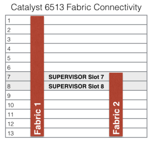
Let’s look at another classic situation, this time using the Catalyst 6500 switch as an example. Before we even choose a line card, you need to be aware that if you have a 6513, only 5 of your linecard slots have dual backplane connections (2 x 20GBps); all others have only a single connection (20Gbps):
From the outset, the line cards that you can install in a 6513 are limited to those compatible with the slot you have free. Let’s assume then that you have a 6509 or smaller, where all slots are dual fabric connected, and you want to install a 10 Gigabit Ethernet card like the WS-X6708–10GE.
Fabric Oversubscription
There’s an obvious issue here which is that even installed in a dual-connected slot (a requirement for this card), there’s only a potential 40Gbps to the backplane fabric, but the card offers 8 x 10GE ports. So at a minimum, we need to understand that we are oversubscribing the backplane by a ratio of 2:1. We’re being very slightly generous here as well – my understanding is that you can’t truly get the full 40Gbps (80Gbps full duplex) to the fabric by the time you figure in overhead and so on. Still, let’s run with it as a decent approximation.
Linecard Architecture
The architecture of the linecard itself is our next challenge. Borrowing from Cisco’s documentation, the 6708 looks like this:
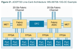 The Port ASICs are capable of 10Gbps full duplex. Note though that each pair of ports feeds to a single FPGA. The pairs – because this is useful to know when you’re allocating your heaviest users – are 1+4, 5+7, 2+3 and 6+8. Obvious, isn’t it? Anyway, that FPGA is not capable of handling the full potential 20Gbps that the Port ASICs can feed to it, and is limited to sending 16Gbps to the Fabric ASIC. So already our “80Gbps” has been chipped away to 48Gbps total, and we know that we can’t put two high throughput users on ports connecting to the same FPGA otherwise they’ll be limited to a 16Gbps aggregate.
Each pair of FPGAs connects to one of the Fabric ASICs. The Fabric ASIC can handle 20Gbps to the backplane, so the 32Gbps available to our two 16Gbps FGPAs is really 20Gbps rather than the theoretical 32Gbps that could be fed to it.
Ah, you say, but what about local switching (between ports on the same card)? As best I can understand it, even between neighboring ports, traffic has to be sent up through the FPGAs, and the quoted maximum local switching rate is “64Gbps” which conveniently seems to be the aggregate capacity of the four 16Gbps FPGAs on the line card. Better than that to the backplane, but you still have to plan the port allocations for your heaviest consumers very careful, and again you should be looking to monitor the aggregate throughput of the port pairs feeding the FPGAs and that of the two port-pairs that through their FPGAs feed each Fabric ASICs. I’d be impressed to find anybody actually doing this level of monitoring today, so if you do it please boast in the comments!
Without understanding the architecture of the backplane and the linecard itself, you can make very bad decisions about where to connect traffic sources even though from the outside they look perfectly reasonable. Even if throughput is not an issue, you may need to consider for redundancy purposes how to make sure ports in an etherchannel, say, don’t rely on the same FPGA. Or wait, is that a bad thing that reduces throughput because they’re separated? I’ll leave you to find that one out for yourself.
Juniper Netscreen 5200
The Netscreen 5200 from a few years ago (rather than the current model) is my final example of why a little knowledge is a bad thing. The 5200 around 2010 with the NS–5000-M management module claimed to have a throughput of 2Gbps (4Gbps full duplex, thank you Marketing Department), though it offered an 8-port Gigabit Ethernet module (NS–5000–8G) for connectivity, and can have up to four aggregate interfaces with up to two ports in each. What I learned the hard way was that the 2Gbps system throughput was not available in quite the way I had imagined.
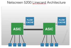
As explained me by JTAC, the architecture on the 8-port GE linecards was something like this (and I’m sure this is a wild simplification):
Each group of 4 ports 0/0–3 and 0/4–7 feeds up to an ASIC, and each ASIC is capable of 1Gbps firewalled throughput supported by a local flow table. Think about that for a moment. With a simple two zone firewall (Trust/Untrust) with a 2GBps aggregate link for each zone, how can you ever get 2GBps of throughput between those zones? Let’s try:
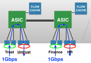
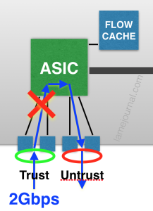 Mmmyeah, that doesn’t work because each ASIC is capped at 1Gbps. In fact there’s no way to get 2Gbps of throughput with a single Trust and Untrust interface. The only way get achieve 2Gbps of throughput is as a aggregate of multiple links/zones arranged to max out each ASIC. For example this would achieve 2Gbps:
 Oh and there’s one more kicker to consider. If you have traffic that traverses both ASICs, it does two things to annoy you:
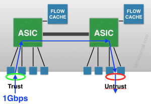 Firstly, that single 1GBps flow from Trust to Untrust just ate up 1Gbps on both ASICs. That’s your “2GBps throughput” gone with only a single gigabit’s worth of traffic. Secondly, because the flows go across both ASICs, the CPUs on the management card have to update the flow cache on both ASICs, and the flow caches have to keep each other in sync with regard to session state, all of which increases CPU utilization in a very negative fashion if you have a high number of sessions. The obvious solution is not to span flows across ASICs; keep them local, as in the first flow diagram.
When you buy a “2Gbps throughput”” firewall, I’ll bet that isn’t what you were thinking is it? Again, knowledge of the underlying architecture turns out to be essential in order to get the most out of that hardware.
Lesson Learned
If you’re going to push any platform anywhere above, say, 50% of its capacity, you really have to understand that platform in a rather nauseating level of detail. This assumes of course that the manufacturer has published that information, which is not always the case. But either way, Patrick’s example of the SRX IOC and the examples I give here of the Catalyst 6500 and the Netscreen 5200 I hope serve to illustrate how something that seems simple on the outside can throw you a curveball because of how it works on the inside.



Great post, food for thought when designing a solution. Biggest problem would be getting that kind of detail from vendors in a reasonable format I’d say. That Sup720 diagram is very familiar and those Cisco Live hardware architecture sessions and freely available slides are the best example of good vendor information sharing. Some of the less well resourced vendors however…I inherited DCs of IBM/BNT switches – documentation isn’t a strong point!
I agree, Steve. This information is not always out there the way it should be, even from Cisco at times. And as you say, it really should be as it is often the difference between a network that works or fails.
Been there, done that. Got burned on screenos too. ugh… Try designing an entire datacenter around an NS5400 at the “core”. Not too mention it doesn’t pass IPX.
I’ve had a data center with a Cisco FWSM as the core router, does that count for anything? 😉
I’m no network engineer, but I have a sense of using the right category of device for the right application.
I’ll best you, how about Netscreen SSG as the border/aggregation router, firewall, core data centre router and switch with no use of VLANs or VRFs. All running 50% VoIP and 50% HTTP traffic, multiple-tenant traffic.
That sounds like my home network! 😉
If truly a production network then, ugh… yikes!
John,
You’ve hit on what I’ve quoted as my own maxim, but is really Rule #1 of Systems Engineering — every system has a bottleneck/chokepoint. Understanding how/when/why they manifest is the key. What you’ve so eloquently pointed out is that not many people bother to think about what is “in the box”… Ignoring that can get you into big trouble, as you mention. Very well written post, as always!
Thanks, Omar. I’ve heard you say that before, and it really is the truth. Identifying where that bottleneck exists is not always straightforward as you know, and doubly so when it sits within a black box where the manufacturers are not always entirely forthcoming about the internal architecture…