There’s no escape from the continuing look at Microsoft Visio ShapeSheets! This post is Part 3 of 3 (although I strongly suspect that in Douglas Adams style I will shortly have to create “Part 4 of 3” to look at some more advanced topics). As a reminder:
In Part 1 I covered some of the underlying terms and concepts required to play with textboxes. I suggest reading this before the other parts, since this is a continuation!
In Part 2 I looked at whether the changes discussed can be implemented without touching a shapesheet in the first place, and look at some of the issues that can arise by doing so.
In Part 3 (this post) I’m looking specifically at how to implement these changes consistently via the ShapeSheet.
First, we have to make the ShapeSheets visible!
The option to view ShapeSheets, like so much fun stuff in the Microsoft Office suite, is considered to be a Developer function and so to protect your innocent minds Microsoft has hidden them from you by default. If it’s any consolation, all of the Office applications have a hidden “Developer Mode” containing access to macros plus some application-specific functions. You’ll know if it’s already enabled in your copy of Visio, as you’ll have a Developer ribbon showing at the right hand side of the ribbon bar names:

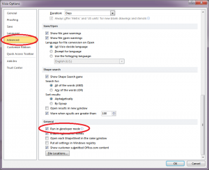
If you don’t see the Developer ribbon, it’s quick to enable. Depending on your version of Visio, go to either the “Office Button” (2007, ugh) or the File Menu (2010), and choose Options. Go to the Advanced options (select on the left), scroll down until you find “Run in developer mode” and check the box. Click ok to save your changes. The menu should appear straight away:

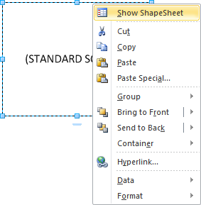
So now we’re running in Developer Mode (feels good doesn’t it?), viewing an object’s ShapeSheet is simple – right-click the object and choose Show ShapeSheet:

Another window will open (usually tiled underneath your original visio workbook) containing the ShapeSheet data:

If you’re lucky, you’ll still see the original object displayed in the top window (but sometimes you have to scroll the regular visio window around so you can see the effect of any changes you make in the ShapeSheet.
The window title is really superbly unhelpful in some ways – it has the title of the Visio workbook (shapesheets.vsd), the title of the tab the object sits on (Part 2), and a reference to the object (Sheet.1). Feeling illuminated? It’s just the way it is. Each object has a unique id on the sheet; this happens to be the first object I created (number 1). Each object therefore will open its own uniquely named ShapeSheet window. However, since there’s nothing here that shouts “This is a square” or anything else that might help you quickly confirm which object’s ShapeSheet you’re looking at, my general rule unless forced otherwise, it to only have one ShapeSheet open at a time. There’s also the matter of ever-diminishing screen-estate to consider, but that’s in many ways almost secondary to how confused I get.
The ShapeSheet itself is somewhat more helpfully laid out; there are sections (each with its own header), with properties (red text) and values (blue text) for each. Of course, nothing is ever as simple as it is consistent, and some values have to be laid out more like a table. For example:

In this case, each row describes the formatting of a block of characters. The first 18 characters are described on the first line; the next 16 on the second, and a final 1 character which appears to indicate the end of the text. Out of interest, that last line apparently containing just 1 character only seems to get created if you format the last letter in the text block in a way other than the default text for the object; very strange behavior which I must look up in more detail at some point to understand why. Anyhow, if you’ve ever wondered how Visio can track multiple text styles within a single object though, this is it – and the more complex your mix of styles and colors, the more lines the Character block will get (rapidly so!). Conversely, if you just use a single text style for the object, there will be a single entry with a zero value in the first column, which implies “All characters”.
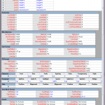
By way of sharing the pain, here’s the default ShapeSheet for a square with some text in it – it’s quite a long list of information, so click through to see it larger and in its full glory:

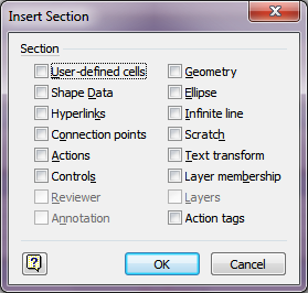
If that’s not bad enough, we’re not even seeing all the possible sections; you can add sections if you need them, from this list:

For the examples we’ve worked through so far, the most common section that needs to be added manually is the Text Transform section, as that’s where the TxtPinX, TxtLocPinX, TxtPinY and TxtLocPinY controls are located. If you manipulate the text box position with the mouse (e.g. by dragging the yellow diamond around), Visio creates the Text Transform section automatically and puts in the appropriate values. If the textbox is in the default position for the shape, the Text Transform section is omitted.
By the way, all of the ‘values’ we’ve seen in the ShapeSheets so far are editable. When you make a change to a value in a ShapeSheet and hit ENTER (or otherwise confirm that you are done changing the field), the change immediately takes effect on the object.
Manipulating Textboxes
In the previous parts, we looked at how Visio aligns textboxes, and how one could to manipulate the position and alignment of the TextBox area of an object using the standard Visio interface. Now we will look at the same tasks performed at the end of Part 1 (the “IDF box” via the ShapeSheet. This time, I will include ShapeSheet excerpts to show the changes that are being made on the way through, limited to the sections we actually care about. First of all you may remember, I drew a square with rounded corners and a dashed red line and added my text “IDF 1”:
 Note that the LinePattern is set to “2” (a dashed line), the color references red – RGB(255,0,0) and the Rounding is set to 0.3125in. Next, I bottom-aligned the text. You don’t have to use a ShapeSheet to do this, but since we’re here:
Recalling the analogy that a textbox is like a piece of paper that we pin to a pinboard, in the next step I changed where I stick the pin through the paper (the “blue pin”), so that rather than being in the middle, it’s now at the bottom of the paper. We achieve this by changing TxtLocPinY to zero (or for laziness, TxtHeight*0). Since the Text Transform section doesn’t exist by default, we’ll have to right click and choose “Insert Section” (or click on “Insert” in the Sections group on the ShapeSheet Tools Design ribbon), and choose Text Transform from the dialog box, before clicking OK and proceeding with the change.
Finally, we wanted to move the textbox so that its bottom was at the top of the square. Since we already are ‘pinning’ the textbox at its bottom, we just need to change where on the board we push the pin in – that is, we change TxtPinY.
In reality, the two steps that are critical to perform in the ShapeSheet are the TextTransform changes. The fact that they are formulae means that they automatically scale with the object size. This was also a fast change – once you’re used to ShapeSheets, it takes only seconds to go in, add a section, change a few values and drop back out again.
I’ll leave it there for this post, and I’ll come back in a future post and look at some more changes that can be made with ShapeSheets. For the moment though, have a play with the values and see what happens – or make a change via the GUI and see if you can figure out what changed in the ShapeSheet. It can be interesting (for some value of interesting between “sad” and “geek”) for example to watch the Characters section of the ShapeSheet as you add and format text within a shape.
If you have any questions, please fire away!


So, why does a change in the shapesheet not reflect in the drawing. Changing the line color from 1 to 9 in the shpesheet does not change the color of the drawing line, at least with the Annotation shape. If I use the line format window it changes the color ant the value in the shapesheet???????
Hi Harry,
The answer is “because Microsoft made it that way” :-/ This KB article (http://support.microsoft.com/kb/827284) mentions thie behavior for Visio 2007, but it works the exact same way in 2010.
As a side note – and maybe slightly more helpful, annotaion objects are really a group – e.g. a box and a line grouped together. If you click on the annotation object, wait a second, then click on the box part of it, you should be able to select just the box sub-object. If you then view that object’s shapesheet, changing the line properties there does affect the box — but not the line part of the annotation, obviously. You can do the same thing to select the line portion of the annotation and make shapesheet changes there too. I fully understand that this is terrifically inconvenient and not likely to be part of a good workflow. For some reason when you use the line tools, Visio actually sets the color in three shapesheets: the group object’s shapesheet, the box’s shapesheet and the line’s shapesheet.
Hope that helps a little, even though I can’t solve the issue you have!
So – I don’t have a solution for your issue, as apparently MS haven’t felt it important enough to fix either…
j.
John: Thank you for a brilliant set of articles. Although I have studied your articles carefully, I still have a problem who’s solution is escapes me.
If you examine the “one to one – mandatory” shape — used in ERD designs,
you’ll not a couple of interesting facts: 1) It really is a composite of two individual shapes. 2) It doesn’t let you change the width of the textbox (outside of a manipulation within the stylesheet) How are these textboxes (2 of them) being blocked from standard edit with the textbox tool?
Thanks,
Charlie Kaufman